Repstrap
Sunday, July 30, 2006
It's alive!
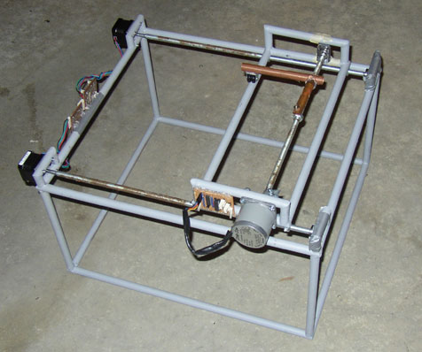
Since I put together the main frame I figured I may as well throw on some of the electronics and take it for a spin. I have just taped the bearing brackets on, but it seems very solid. I'm not even sure I'll need to screw it on.
The motors are screwed on and fit very nicely. I came up with a neat trick that ensures the drill holes line up perfectly with the motor mouting holes, even when drilling with a hand drill. I'll wiki it when I write up the process.
I put the X axis assembly on too. Yes, that's the thing I built a year ago! Good grief...
I greased it up, attached a pen, switched it on and drew a square:
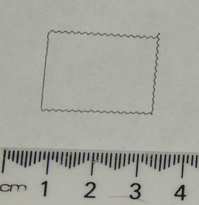
The paper slipped, so it didn't quite match up.
There is a wobble almost a millimetre in size. This is caused by a not-quite-straight piece of studding that I haven't tried to straighten out yet.
I suppose I can't leave it without trying the hexagon test shape. It goes something like this:
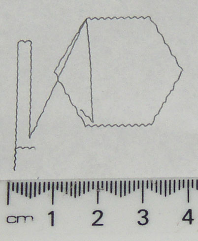
It's not quite perfect yet, but it's something though...
- posted by Simon McAuliffe @ 11:18
Motor brackets added
 Today in a bit of a break from work, I added the motor mounting brackets and gave it a quick coat of paint so it doesn't look so ugly.
- posted by Simon McAuliffe @ 05:39
Friday, July 21, 2006
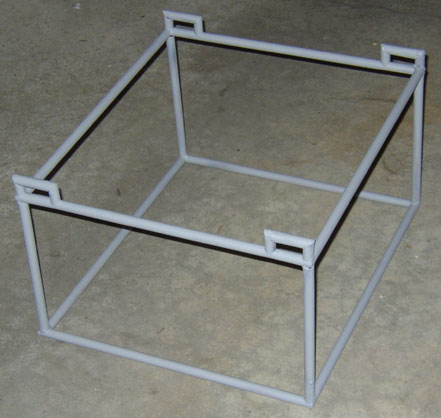
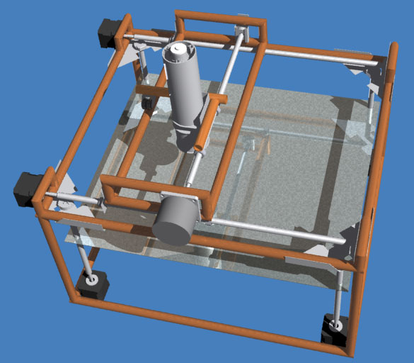
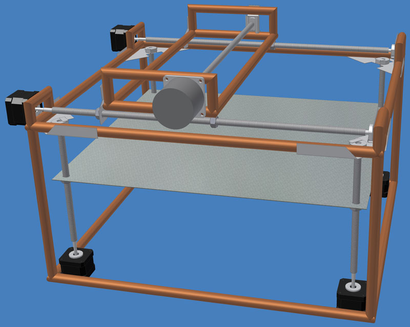
Frame

This is the frame I brazed together a few weeks ago. It just needs a little more tubing added for the Y axis motor supports and then it should be about good to go. Hopefully I'll get the tubing today, but may not have any time to do anything useful -- real work and all that.
I see there was a nice idea on the main blog yesterday which was to use compressed air to drive the piston instead of a motor. It should be able to get much better pressure. It should also fit fairly easily onto the same general scheme for my extruder without throwing it all out, so if my motor doesn't have enough oomph, I can switch to that.
I'll also be using preformed cylinders of CAPA as feedstock (so there are no bubbles). They should fit fairly snugly into the heater tube and possibly taper very slightly towards the top, so that as they are compressed or melt down any air that wants to escape around the outside can do so.
For the RepStrap I hope to get away with a slightly less fine extrusion size than a general purpose final RepRap. That may reduce the pressure requirements a little for my purposes and may allow extrusion with the little motors.
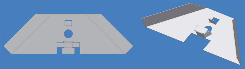
This is how I produced the brackets. Just print out the pattern (from PDF file), and cut it out with some snips. Here's one that's just started:
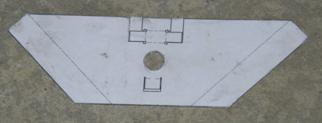
And here's the final result. They're pretty rough because I'm not too concerned about how pretty it is. They fit the bearings very snugly though and seem perfectly functional. The bearings just slot into place.
Some final bending of the corner brackets (the mounting flange) will be needed after they are in place to make it fit as closely as possible.
- posted by Simon McAuliffe @ 21:53
Extruder idea
I'm toying with the idea of using a syringe approach in the repstrapped extruder. I'm a bit concerned about air bubbles, but will have to try it.
It would fit the machine something like this.
I'm using a Tamiya planetary gearbox that appears to be readily available all around the world. The planetary gearbox is great because it spreads the load across more than one gear to reduce stresses and it's all in-line. So that means the motor can move up and down as it drives the syringe without getting too much in the way of other things.
The motor drives a threaded rod that goes through a nut, which causes the whole motor assembly to drive up or down. Guides prevent the motor body from turning so it can only go up or down.
Here's a diagram of the whole as well as a cut-away picture and a picture without the PVC pipe and thermal mass. Click the images for a close-up.

It doesn't hold a huge volume, but this is just an experiment. The three nuts connecting the top half to the bottom half can be removed to re-fill the heater tube.
- posted by Simon McAuliffe @ 10:40
Sunday, July 09, 2006
Frame design update
This is what I'm currently working on slowly building. This is a minor revision based on something Adrian mentioned. Previously the whole X/Y head assembly moved up and down, but now the platform moves up and down instead and the X/Y assembly stays where it is. The advantage of this is that it prevents having a chain of 3 dimensions all dependent on a single stage. So it should be more stable and accurate. The disadvantage is that it can no longer produce parts bigger than itself, but that's not too important at this stage.
In addition to the little bearing bracket pictured in the previous posting, there are two new brackets for holding other bearings. These are just made by cutting and bending scraps of metal.

And also, for the Z axis bearings:
- posted by Simon McAuliffe @ 02:03
