Repstrap
Saturday, November 04, 2006
Firehose
I made a larger "firehose" nozzle with a 1mm extrusion size. It's certainly less finnicky than the 0.6mm nozzle.
There's a few parameters that need fine tuning, but this is a good start.
One slight problem is that the hex test pattern is no longer correctly converted in the host software now because it's a bit out of date, so it's time to move onto some real STL objects while fine tuning.
- posted by Simon McAuliffe @ 02:07
Thursday, November 02, 2006
Repstraps are go
I finally got a chance to sit down and bore out the centre of the axes so I can insert a pin. That fits into the end of the motor shaft and holds everything in-line which pretty much eliminates the wobble. There is still a very small amount but it won't affect things too much I hope. I will remove the remaining wobble later by making properly fitting pins (the current ones are just a little bit loose).
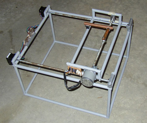
So apart from that and realising my Z axis positive was in the wrong direction, which I fixed, the machine is all finished.
I am using an MDF platform with another piece of MDF on top, which is the actual working surface.
The limit sensors are hooked up and all systems are go. Everything is working very nicely.
The only thing that remains is I'm missing a few screws, so one of the X axis brackets it partly held in place by a clamp and the Z axis bearing mounts are held in place by duct tape, but it holds quite nicely. I'll buy a few nuts and bolts one day soon to clean it up a bit.
From the angle in the photo, the cabling looks like a bit of a tangle, but it actually keeps pretty clear of the platform throughout the travel.

- posted by Simon McAuliffe @ 10:00
Saturday, August 12, 2006
Progress on extruder
I had a conference this week so didn't do much again. This morning I afghan-lathed the PTFE rod, heater tube and nozzle. So that's the extruder complete now except for the heater wire/thermistor.
It looks like some weird laser pistol or something.
- posted by Simon McAuliffe @ 03:54
Sunday, August 06, 2006
Extruder
I'm starting with the Mk II extruder before I embark on making a Repstrappable version.
I assembled the top portion today. It took quite a while to do because it requires some lathing. The bottom half can wait for another day.
- posted by Simon McAuliffe @ 07:49
Saturday, August 05, 2006
Wobble reduced
I did a little fiddling and reduced the wobble:
It's around half a millimetre but it still needs improving. The problem is caused by the connection between the motor shaft and the studding shaft, which is slightly off-center. That's because I'm using plastic tubing to connect the two and the weight of the X axis assembly distorts the plastic tubing. It holds the distorted shape to some degree so it wobbles.
The X axis wobble is essentially completely gone now and that was the worst before, so this is a good step. It needs some more work. I may be able to re-inforce the tubing so it doesn't distort.
- posted by Simon McAuliffe @ 07:07
Sunday, July 30, 2006
It's alive!
Since I put together the main frame I figured I may as well throw on some of the electronics and take it for a spin. I have just taped the bearing brackets on, but it seems very solid. I'm not even sure I'll need to screw it on.
The motors are screwed on and fit very nicely. I came up with a neat trick that ensures the drill holes line up perfectly with the motor mouting holes, even when drilling with a hand drill. I'll wiki it when I write up the process.
I put the X axis assembly on too. Yes, that's the thing I built a year ago! Good grief...
I greased it up, attached a pen, switched it on and drew a square:
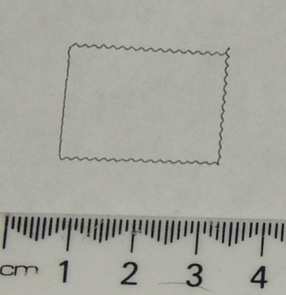
The paper slipped, so it didn't quite match up.
There is a wobble almost a millimetre in size. This is caused by a not-quite-straight piece of studding that I haven't tried to straighten out yet.
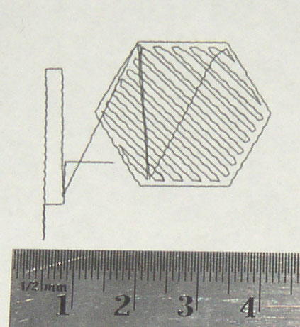
I suppose I can't leave it without trying the hexagon test shape. It goes something like this:
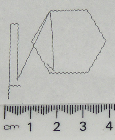
It's not quite perfect yet, but it's something though...
- posted by Simon McAuliffe @ 11:18
Motor brackets added
 Today in a bit of a break from work, I added the motor mounting brackets and gave it a quick coat of paint so it doesn't look so ugly.
- posted by Simon McAuliffe @ 05:39
Friday, July 21, 2006
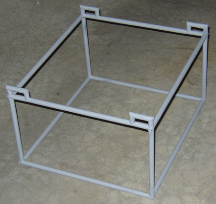
Frame

This is the frame I brazed together a few weeks ago. It just needs a little more tubing added for the Y axis motor supports and then it should be about good to go. Hopefully I'll get the tubing today, but may not have any time to do anything useful -- real work and all that.
I see there was a nice idea on the main blog yesterday which was to use compressed air to drive the piston instead of a motor. It should be able to get much better pressure. It should also fit fairly easily onto the same general scheme for my extruder without throwing it all out, so if my motor doesn't have enough oomph, I can switch to that.
I'll also be using preformed cylinders of CAPA as feedstock (so there are no bubbles). They should fit fairly snugly into the heater tube and possibly taper very slightly towards the top, so that as they are compressed or melt down any air that wants to escape around the outside can do so.
For the RepStrap I hope to get away with a slightly less fine extrusion size than a general purpose final RepRap. That may reduce the pressure requirements a little for my purposes and may allow extrusion with the little motors.
This is how I produced the brackets. Just print out the pattern (from PDF file), and cut it out with some snips. Here's one that's just started:
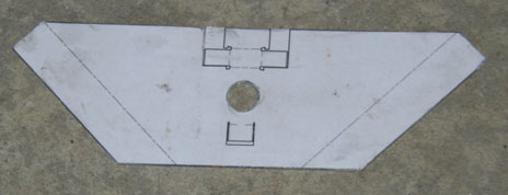
And here's the final result. They're pretty rough because I'm not too concerned about how pretty it is. They fit the bearings very snugly though and seem perfectly functional. The bearings just slot into place.
Some final bending of the corner brackets (the mounting flange) will be needed after they are in place to make it fit as closely as possible.
- posted by Simon McAuliffe @ 21:53
Extruder idea
I'm toying with the idea of using a syringe approach in the repstrapped extruder. I'm a bit concerned about air bubbles, but will have to try it.
It would fit the machine something like this.
I'm using a Tamiya planetary gearbox that appears to be readily available all around the world. The planetary gearbox is great because it spreads the load across more than one gear to reduce stresses and it's all in-line. So that means the motor can move up and down as it drives the syringe without getting too much in the way of other things.
The motor drives a threaded rod that goes through a nut, which causes the whole motor assembly to drive up or down. Guides prevent the motor body from turning so it can only go up or down.
Here's a diagram of the whole as well as a cut-away picture and a picture without the PVC pipe and thermal mass. Click the images for a close-up.

It doesn't hold a huge volume, but this is just an experiment. The three nuts connecting the top half to the bottom half can be removed to re-fill the heater tube.
- posted by Simon McAuliffe @ 10:40
Sunday, July 09, 2006
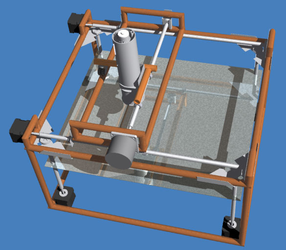
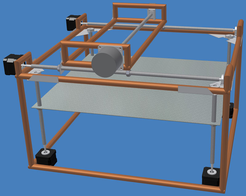
Frame design update
This is what I'm currently working on slowly building. This is a minor revision based on something Adrian mentioned. Previously the whole X/Y head assembly moved up and down, but now the platform moves up and down instead and the X/Y assembly stays where it is. The advantage of this is that it prevents having a chain of 3 dimensions all dependent on a single stage. So it should be more stable and accurate. The disadvantage is that it can no longer produce parts bigger than itself, but that's not too important at this stage.
In addition to the little bearing bracket pictured in the previous posting, there are two new brackets for holding other bearings. These are just made by cutting and bending scraps of metal.

And also, for the Z axis bearings:
- posted by Simon McAuliffe @ 02:03
Sunday, June 18, 2006
X-axis assembly

I've been working on the firmware and controller software for so long now that there hasn't been much progress on my repstrap. This weekend I thought I better do something useful, so I put together an X axis assembly.
This uses a bearing at one end now for a smooth movement, and plastic tubing to connect the motor to the shaft. Each end of the shaft is lathed and polished using the Afghan method.
There will only be one drive rod on the X assembly. The extruder will be held in place by two nuts on the threaded rod, one of which will be anti-backlashed.
The other side of the extruder will be supported by a wheel that runs along the far side support. Alternatively, a steel rod could be added if that turns out not to be smooth enough. I have a pair of small wheels from a caster that will stay centred over the tubing, so I'll try that first.
Is is made entirely from plumbers copper tubing and is spray painted with grey primer to prevent the ugly copper tarnishing.
- posted by Simon McAuliffe @ 00:38
Wednesday, January 04, 2006
Motor controller board
Some progress has been made on the RepRap motor controller software and hardware, so it can be stolen for use in the RepStrap too. Although for RepRap it is likely to be fabricated in the future by the RepRap itself, initially it might be a PCB (not yet decided).
However, for Repstrap it needs to be easily fabricated from readily available parts, and although making PCBs isn't very hard it will be simpler and require less equipment if we use stripboard. So with that in mind, I have built motor controllers for Repstrap out of stripboard.

This photo shows the underside of the stripboard for the motor X axis controller after drilling out the unwanted copper points. The Y and Z controllers are essentially the same.

Here, after soldering the components in. There is a heavier duty wire for the ground and 12V to the stepper motor driver.
Full details (and software) will be posted later. They are also available as part of the main RepRap project.
The parts required:
1xPIC16F628A (@NZ$5.24)
1x15V 1W Zener, 1N4744 or similar (@NZ$0.48)
2x1k resistor (@NZ$0.05)
2x4.7k resistor (@NZ$0.05)
1xULN2803A darlington driver (@NZ$4.98)
1x18 pin DIP socket (@NZ$0.54)
1x25 way header pins (@NZ$1.48)
Some wire (perhaps NZ$0.20)
A piece of stripboard around 21x16 in size (perhaps NZ$1.00)
Some solder, etc (maybe NZ$0.05)
Total cost: NZ$14.17
There will be one of these for each of the three motors, along with a controller for the extruder which will be a similar price, and a general common interface module, which will again probably be around the same price. So the electronics are looking at costing approximately NZ$70.
Scrounging parts will bring this down a bit of course.
- posted by Simon McAuliffe @ 09:25
Sunday, August 14, 2005
Threaded guide rods
 I haven't made much progress on things for a bit because I've been busy building myself a house. Here's the basic setup I'm using for lathing the threaded rod.
I'm using a drill press here, but a regular drill will work just as well (see Vik's Afhgan Lathe documentation). The only real difference with this is that I'm lathing vertically rather than horizontally.
At the opposite end to the drill head there is another drill chuck to grip the other end of the rod (this is essential). What makes this different from the Afghan method described for drilling a centred hole is that this is a rotating chuck. I took this off a dead rechargeable drill that I picked up for $2 from the junk yard. I just removed the internals and then cut it with a hacksaw so only the front part of drill remained. After putting the first gear back into the drill (which includes the greased bushings, etc), I end up with a smoothly rotating chuck. As pictured, I clamped this to the bench. You can quite easily adjust the position of this by hand while the drill is spinning. Any wobble in the rod should be eliminated and you can also easily see if the rod isn't straight.
The platform serves as a good tool guide, and I use this to help position a metal file. I lathe it as described in a previous post. I chose 6.0mm as a good diameter for the end of the shaft. The rod is M10 (10mm outer diameter) so 6mm will give enough room for adjustment in the bushing and will still be strong enough. Care needs to be taken to ensure the lathed part of the rod is parallel. If it widens towards the tip, it won't be able to be removed from the bushing later on. If it tapers at the tip, it is more likely to jam. Still given a choice, it'll be better to taper slightly than become wider. Using callipers, I lathed to 6.0mm at the tip and 6.05 towards the thread.
The lathing happens slightly away from the end of the rod (because part of it is held in the chuck). After lathing and polishing, I cut the threaded end off. You repeat for each end, ensuring the total length is correct. The only thing that remains is to polish the end of the rods when the excess thread is cut off. This is fairly important because if it's not rotationally symmetric it will dig into the back of the bushing which will add unwanted horizontal play into the shaft.
I have a method ready to try this but haven't quite got there yet.
Also, as shown in the picture, the rod I'm trying to lathe is too tall for my drill press, so I've raised it up onto a base supported by some blocks, and I had to rotate the drill head away from the base.
- posted by Simon McAuliffe @ 09:20
Saturday, July 30, 2005
Molding and PLA extrusion
I tried vaseline as an alternative release agent and the whole molding/casting process worked a lot better. The plastic removes cleanly and there is no discolouration. The method involved heating the vaseline to make it a thin liquid. It was then painted onto the surface. Heating the plaster of paris absorbs some of the vaseline, so another application was added to ensure some at the surface.
The plastic is very viscous when melted and extremely hard when set. This leads to two concerns I currently have. One is that it may not flow through a narrow diameter extrusion nozzle. The other is that it is so hard that the screw-based feed mechanism may not be able to reliably grip onto rods of PLA (unlike EVA, which is quite soft so easy to feed).
I've had a slightly different idea for extruding PLA. It probably won't be useful in a reprap situation but it may be useful as an interim method in the repstrap. The idea is to have a narrow tube (15mm copper tubing) that opens in a larger diameter tube above it, which serves as a hopper. A nozzle would be attached to the 15mm copper tubing. A 12mm auger bit running in reverse goes through the hopper and down into the tube. The whole thing is heated via nichrome wire to melt PLA. Because the PLA is quite viscous, rotating the auger downwards should push the melted plastic downwards, forcing it out of the nozzle. The advantage of this approach is that you can feed almost any form of PLA into the hopper and it will be extruded. This means you don't need to prepare rods and you can use granules, chips or powder. It also makes recycling easy because you just break up the original plastic part and drop it in the hopper.
- posted by Simon McAuliffe @ 10:22
Friday, July 29, 2005
PLA fidelity
 I thought I'd try a little experiment to see how well PLA will take on small detailed shapes.
This evening I cast a gear into a plaster of paris mold of a spur gear. I put PLA granules into the mold. I heated everything to a little over 200°C and waited. The PLA melted and formed an amorphous blob but it wouldn't reach into the teeth of the gear. A little disappointing, so I removed it from the heat and left it to cool. Interestingly in the process of cooling, the plastic was drawn into the finest details of the gear. Something about the cooling process really helped. I don't know what this means for extrusion or if it helps at all.
The result is extremely accurate and detailed and you can see very fine details of the involute tooth shape (not very apparent from the photo). There were a couple of little bubbles but they were well away from the centre and the teeth and it seems very hard and strong. It meshes very nicely with matching gears with no slop.
I coated the plaster of paris with a cooking oil spray to act as a release agent for the mold, but it failed pretty abismally. It was too hot for the oil I guess, and it led to the brown discolouration as the oil denatured (along with an unpleasant smell that filled the house). The plaster didn't release as it should and I had to break it off and scrape and brush the remaining plaster off.
The mold making was probably fairly critical to the detailed result, but we're not really interested in molding parts right now, so I won't go into detail.
- posted by Simon McAuliffe @ 10:00
Thursday, July 28, 2005
PLA
How exciting. After a mix-up with NZ Post, a sample of 210g of PLA arrived for me to play with today. Thanks Vik!
I thought I'd check out the behaviour of the PLA. It turns out it melts at a much higher temperature than I expected. I expected it would melt between 130°C and 180°C. Here's what I found:
155°C starts to become noticably glassy, but granules are still quite hard.
170°C starts to deform
180°C granules merge together very slowly (still too viscous to flow in any useful way)
185°C slowly flattens to a single continuous mixture, but still very viscous. Quite meldable at this stage though.
200°C still quite viscous
230°C still quite viscous. I'm not sure it will extrude easily at <1mm thicknesses.
At this point there was a little bit of a smell, so I thought I wouldn't push it too much futher. Beyond this point becomes less useful in any case.
As far as mechanical properties, this stuff is very tough. Should certainly do a good job for a lot of parts. It's a bit harder than I expected, but also more brittle. I think those are usually traded off against each other, so no big surprise. If we can make our own, we may be able to tailor that to our taste. The brittleness doesn't seem like a problem, you have to apply quite a lot of force to crack it.
I also discovered it adheres really well to things. The small sample I melted in a ceramic container wasn't coming out and reheating only gets some of it out. I thought I'd try breaking the container around it on the offchance it would come free. It's well and truly bonded however, so that sample is ruined (getting the fragments of ceramic out will be next to impossible now). Something not to try again...
Good adhesion is a promising sign really since it means objects we create will probably be strong (lots of extruded rows need to bond together).
- posted by Simon McAuliffe @ 08:56
Tuesday, July 26, 2005
Gear cutting
I thought I should note down an idea I had a few days ago before I forget. The turntable platform will have precise control of it's angle, so it would make for an ideal gear cutting tool. If a blank made of plastic or metal was mounted on a support above the centre of the turntable, a simple cutting tool could be used to produce custom gears. The cutting tool could just be on an adjustable up/down pivot and hand operated. The computer would set the angle, then you'd just swing the cutter up and down and proceed to the next tooth.
This might be particularly useful, for example, to produce bevel gears for the extruder and using only simple radial gears to construct the turntable.
Custom gear cutting would also make it plausible to construct a gear that can mesh with a worm gear that is made from threaded steel rod. It would need to be made of steel and have small teeth, but that might be one easy way to get worm gearing. Perhaps the larger pitch coach screws could even be used (?).
Of course, this could all potentially be automated in the future too, but I'm just thinking of construction of a basic machine for now.
- posted by Simon McAuliffe @ 07:54
Bushing support
 The support nut for the bushing is created by drilling a 6mm hole through the middle of the pipe. The hole is widened to snugly accomodate an M6 nut. Then an M6x20 bolt is put through the hole and fastened with the nut.
The purpose of this design is to hold the bushing in an accurate position. It can be removed (which you need to do if you want to take the extruder assembly off), and then put back in exactly the same place without recalibrating anything (hopefully). The top point of the nut should be marked so that you can ensure you put it on in the same orientation when re-assembling.
The groove obviously only needs to be cut in a rectangular shape with a straight metal file because the sides of the hex nut are parallel (this means it slides up or down to disassemble). The depth isn't too important. It just needs to be deep enough to key the nut nice and accurately without any chance of slipping, but it can be quite deep too because the top and bottom of the tubing will support it even if you cut all the way through the copper. It should also only be on the inner side of the tubing, otherwise it can't be tightened. The filing should be done slowly and checked frequently so that there is no slop in the nut positioning.
Any excess bolt length can be cut/ground to sit roughly flush with the end of the bolt. The exact position of this is not critical.
 The next step is to attach a larger M10 nut to the M6 nut, which will be the bushing housing. To begin with, you only want a temporary joint (rather than brazing them together) because you might need to adjust their relative positions to correct for manufacturing errors. I am just using a hot glue gun because the "glue" can be peeled off cleanly afterwards so it won't interfere with the brazing. Later on, once the final position is determined and glued in place the nuts can be removed and then clamped together. The glue can be peeled off and then the nuts cleaned and brazed.
- posted by Simon McAuliffe @ 07:30
Monday, July 25, 2005
Extruder feeder screws
 I was picking up a few M6 nuts and bolts for the repstrap bushing connector and grabbed several of these at the same time.
They have a high pitch thread which means they can be used on quite a high angle while still resulting in the thread running more or less horizontally. That means a fairly short length such as these should be quite workable in the scheme outlined earlier.
These M8x75 galvanised coach screws are readily available from even a small hardware store.
With a little machining these should turn into quite good parts. It remains to be seen if they will bind with PLA/PHB rods sufficiently well to draw them downwards strongly enough.
- posted by Simon McAuliffe @ 10:05
Sunday, July 24, 2005
Bushings
To keep things simple my concept of the head assembly uses threaded rod and nuts (see overview diagram at the start of the project). However this means the threaded rod must rotate smoothly. For simplicity's sake, I plan to use high density plastic bushings. This requires that
a. the plastic is not affected by oil; and
b. that the threaded rod is very smooth at the end.
To check the practicality of (b) I did a little experimenting today. Using just an electric drill I wanted to produce a high polish on the end of a threaded rod. This is based on the afghan lathe technique with minor variations.
 The first step was to remove the threading. This was just done by lathing with a metal file held on a support (using the drill as a lathe). The shaft is then smoothed to a high polish by using sandpaper. Starting with a moderately coarse paper and reducing a little at a time down to a very fine paper. I finished with a #2000 paper, which produces a very smooth surface.
 The end of the shaft can be cut next. It can be polished and the edge rounded too, to prevent any binding in the bushing. This is done in the lathe again.
The idea now (which I haven't tried yet) is to drill a hole in the copper pipe. On the inner side of the pipe the cut will be widened so that a nut can be slightly inset into the groove to prevent it from turning. I really need a deeper nut than a regular nut because the bolt will come in from the other side of the copper pipe and go into the nut, but I want some free space inside the nut cavity, so I'll be brazing two nuts together. Now you can bolt the nuts onto the copper pipe. Fit the polished end of the shaft into the gap, and ensure everything is in exactly the correct position. Fill the rest of the nut cavity with melted thermoplastic and let it set. Then just turn the shaft and it should come free. Oil it and you have a perfectly snug fitting bushing that will rotate without any slop. The main advantage of this approach is that any construction errors will be corrected for by the plastic bushing being set in the correct position -- provided the errors aren't so large that the shaft doesn't fit inside the nut cavity at all. In that case, you can braze your two nuts together offset slightly from each other to correct the majority of the error and use the plastic to fine-tune the final position.
That's the idea anyway. I considered literally more than 50 different ways of connecting the shaft to the pipe, but when this extremely simple idea eventually came to me (simple ideas are sometimes not easy to come by), it seemed like a good way to proceed.
 If it doesn't turn out to work as well as I hope, I can always fall back to using bearings. I was in the scrap yard shop the other day and picked up a pair of old roller skates (not roller blades) for $2. These are great! Inside each of the wheels there are two bearings, so for a pair of skates, that's 8 wheels or 16 bearings. Great value at around 12c each.
 So as a backup I thought I'd try to cut a slot into the shaft. I just did this by lathing with a hacksaw, which was held square by supports . A C-washer can be put into the slot as shown.
 So with the C-washer clipped on, it fits nicely into the bearing (of course I actually cheated a little here because I knew the bearing size in advance). If I mount the bearing on the copper pipe, this will make an even better and smoother-running shaft. I haven't worked out a good way of mounting it yet, but it shouldn't be too hard. The general idea is to use three screws to hold the bearing in place so its exact position can be adjusted, or perhaps use thermoplastic again to hold it in just the right position. If I use bearings, the polish obviously isn't necessary, but it just looks so pretty :) Still I'd prefer the simplicity of the bushing. Perhaps not everybody can find old roller skates these days.
This was all just a test. For the final bushing, I think a smaller diameter would be better. For a bushing, the larger the diameter, the greater the friction. So you really want the smoothed shaft end to be as small as possible while still being sufficiently strong that it won't bend or wobble. That will depend on the eventual head assembly's weight which I don't know, but at least a bit smaller than pictured would make sense.
Something not obvious from these pictures is the use of liberal amounts of light lubricant during the cutting and polishing. I just cleaned it off before taking the photos.
- posted by Simon McAuliffe @ 04:17
Saturday, July 09, 2005
Material feeder
While I remember, I was thinking about a possible enhancement to one of Vik's ideas for using a threaded rod (or bolt) to draw feedstock into the extruder.

The main purpose of this is to eliminate the need for bending the feedstock rod. In fact by slanting the thread by the same angle as its pitch, then the force drawing the feedstock downwards may be more efficiently applied (as in the diagram, the threads end up being completely horizontal). To get more angle, you could slant the threaded rod at twice the thread pitch and still be no worse off than having it completely vertical.
By also facing the low ends of the threads towards each other, it leaves more space for gearing to drive the threads. It will probably require bevel gears to make this work nicely. The downside is that this will also produce a sideways force, but the rod needs to be passed down a tube in any case so this will keep the feedstock moving vertically only. At the same time, with the thread in the right direction, there is also a sideways force in the opposite direction. [Do they come close to cancelling out?]
The points in the diagram marked with a * indicate a point where a bearing or bushing is required.
- posted by Simon McAuliffe @ 07:02
Tuesday, July 05, 2005
Levelling the platform
A few days ago I was taking apart a broken VCR for parts (I can get these for a couple of dollars at the scrap yard and they contain some useful parts like gearing etc.). One interesting idea they use for calibrating the spin axis of the head is to use three small adjustment screws.
Three obviously seems the best number. Two doesn't give it stability or the ability to adjust in one direction and four would require coordinated adjustment without any apparent benefit, and is likely to just damage the screws.
So what I'm planning on doing is attaching a triangle shaped piece of metal to the top of my turntable shaft. The corners of the triangle will be attached to the non-stick pizza tray (turntable) by screws. Small adjustments in the screws will allow me to get a nicely flat spinning turntable.
Similarly, the extruder platform will need some adjustments to ensure it is perfectly parallel to the turntable surface. I will do something similar to connect the top half of the frame to the bottom half so that it is also adjustable. To keep things simple, I will probably have to use 4 adjustable connectors.
- posted by Simon McAuliffe @ 10:20
Building a frame
I've been spending my recent time writing communications infrastructure for a PIC-based network of devices. That's gone pretty well and amongst other things, we now have a working distributed controller for a motor. That means I really need to make some progress building this contraption so I have a use for the new motor controllers.
I have recently realised that Vik's contributions to the reprap project parallel some of my intentions, and involve building a working prototyping machine to produce reprap parts. That makes this project rather superfluous, especially now that some of the experimental ideas (such as threaded rods and nuts for producing movement) are being used there too. That makes it less useful for me to experiment with the same ideas, but I'm going to continue anyway as there are still some slightly different ideas, and I still want a machine for myself.
With that in mind, this evening I brazed together the top part of the frame for my concept:

It was my first attempt at brazing and it turned out to be easier than I expected (certainly easier than welding). I was using an oxy-acetylene welder at a fairly low heat, but a small/cheap gas torch should work just as well.
The trick is to evenly heat the surrounding pipe until it has a bit of a red glow. This is still well below the melting point of the copper. Then just touch the brazing rod onto the surface and it flows quite easily and nicely into the gaps. The result seems really quite strong.
I used duct tape to hold the parts in place while I welded. Copper conducts heat very quickly, so I put a wet towel over parts with the duct tape to prevent it from burning. For the first joint, I taped the tube to the side of a square brick to provide a good right-angle. From there on the angles pretty much just work out provided the tube lengths and cuts are fairly accurate. The only thing to be careful of is ensuring the frame sits flat and isn't twisted at all.
If anybody repeats this, take some care cutting the pipes at 45 degree angles. The closer you are the easier the joint will be to make. I found that using a large protractor I could get the angle to within 2 degrees or less, and the joints are quite close. I just cut the angles by eye, which I found I could reliably do to within about 10 degrees after a few. After that, I used a grinder to fine tune the angle. A regular old metal file works fine too, but it's a bit slower. Spend the time to get the angles right in the first place and make sure the ends of a pipe slope in the same plane.
- posted by Simon McAuliffe @ 09:39
Friday, June 24, 2005
Communications
Last weekend I gathered some bits and pieces from some old dead printers so I now have some stepper motors and gearing. None of the parts are ideal, but it should be enough to get a prototype working from. Unfortunately I discovered I was out of brazing rod, so I didn't make any progress with putting anything real together. I might be able to get out to the hardware shop this weekend if all goes well.
In the meantime, I've been discussing communications ideas with Adrian and Vik and after a few days of tinkering I now have a prototype comms library that does the right thing in the emulator. If I don't build mechanics this weekend, I'll probably breadboard this and run it on some real PICs.
The implementation is currently a token-ring-like system based around asynchronous serial communications. The packet structure is based on a small open system called SNAP. I have a few reservations about the design and suitability of SNAP now, but it's partially implemented so I'll put up with it for now. It's all fully interrupt driven and deals with most stuff automatically in the background, so it should make building the various controllers a straightforward task.
There are future plans to probably replace the token ring system with an i2c based system which will improve latency and speed. This should be sufficient for early experimentation however.
It's all built in sdcc, which has a few small glitches, but so far I've managed to work around all the problems and things are progressing well. It's on a CVS server, but not available publicly at the moment. Perhaps it will move to sourceforge or some place like that in the near future.
- posted by Simon McAuliffe @ 11:59
Friday, June 17, 2005
Gearing
Earlier this week after contacting a bunch of suppliers, I gave up trying to find a good source of gearing, but all is not lost. A lot of gearing can be found in old equipment. The older the equipment, generally the better -- they used to build things really well. Daisy-wheel and similar printers are about the best but an old dead laser printer or even a VCR will likely be a source of something usable.
At this stage without a reliable and repeatable source of affordable gears, I'm going to get the parts from scrap since I already have quite a bit. You can get old broken printers and VCRs for a few dollars. The downside is that the entire machine won't be exactly repeatable, but will still work with other gearing with very minor modifications.
- posted by Simon McAuliffe @ 07:04
Monday, June 13, 2005
Gearing
It seems very hard to find the worm gears (and matching spur gears).
I can't currently find anyone that sells these at anything but rip-off prices (such as RS components). Making them will probably be problematic given only simple tools.
- posted by Simon McAuliffe @ 09:54
Sunday, June 12, 2005
Preliminary design
I experimented with a few different layouts to see what could fit where. This is a little time consuming in CAD but it sure beats building and throwing away real parts.
A few designs were considered including:
- A pivoting arm (like a record player)
- "Dave's design"
- A 3-axis plotter
The threaded rod was selected because it is readily available at a hardware store (whereas racks are not). This also provides some degree of gearing.
Tubing is being considered for the general chassis construction because it is an innately strong shape, readily available and pretty cheap. On the downside, it's not very easy to work with. I was hoping to find something other than copper which may be a bit too ductile and might deform, but steel or brass tubing was harder to find. Copper can be brazed together with just a cheap gas torch. This will unfortunately be fairly labour intensive.
These diagrams are just roughing out the design at this stage, and some bearing and supports are not shown yet.
This is a general overview (rough layout only):

A slightly closer look underneath the turntable:

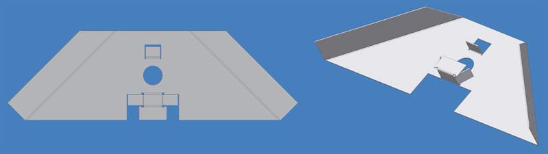
And a closer look at the extrusion platform:

incidentally, the round brass things are supposed to represent spur gears, I just didn't want to spend time modelling them.
Concerns:
- If there is any inaccuracy in the machining of the threaded rods or the worm gears, there may be some jamming. If this occurs, it would be preferable to use only two nuts on the platform rather than 4. This would make the platform less steady, so an additional polished rail would probably need to be added with a bearing sleeve attaching the platform to the rail. This would be at the opposite end of the platform from the nuts.
- The platform raising mechanism depends on a vertical slot cut in the copper pipe. A pin through the threaded rod sits through the slot to lock the rotation of the rod and pipe while allowing the rod to rise and fall. I'm not sure at this stage how easy it will be to accurately cut this slot. It needs to closely fit the pin to prevent a rotational hysteresis type effect. Perhaps there is a better mechanism to allow the platform rotation and raising.
- Having one motor that controls both height and rotation of the turntable is a nice simplifying idea from Reprap, but it does rely on the quantity of material deposited from the extruder matching the change in height of the platform after one revolution. I'm not sure how realistic this is. It sounds like too much material for accurate production, but we'll see as it progresses.
- posted by Simon McAuliffe @ 08:23
Saturday, June 11, 2005
Component placement
Here's an idea I had for a slightly different way of attaching components to a reprap that may improve bonding and electrical properties.

click for a larger image
Another advantage of this approach is that you can potentially have multiple layers of components, making use of three dimensions rather than just two. This could be quite beneficial given the small scale integration density of the RP approach. Unfortunately this would require human intervention for each layer. Of course once the basic system is working, no doubt others will build add-ons to automate more of the process, so a little human intervention isn't much of a disadvantage in the early days.
- posted by Simon McAuliffe @ 06:27
Parts costs
I went and looked at some bits that might be useful.
300mm non-stick pizza tray: $3.99 (Warehouse)
M10x1m threaded steel rod: $6.50 (Bunnings)
M10 steel nuts: $0.16 (Bunnings)
M12x50x50x3 square steel washer: $0.80 (Bunnings)
Copper tube 15mm x 1.02mm x 1m: $9.06 (Bunnings)
- posted by Simon McAuliffe @ 03:22
Friday, June 10, 2005
Purpose
This blog relates to the Repstrap project. The Repstrap project is related to the RepRap project and aims to build a boot-strapping system with sufficient capability to produce the parts needed to build a seed RepRap machine.
For those such as myself that are not lucky enough to have access to a rapid prototyping machine this will hopefully provide a means of getting involved in practical development with RepRap at an earlier stage.
Goals:
- Should be able to produce reprap parts at similar levels of accuracy.
- Should be possible to construct with low cost and off-the-shelf parts.
- Should use similar principles to reprap so that any software produced can be re-used in some way for the reprap project.
- Does not need to be built to last (once reprap parts are produced, it is no longer needed).
- Should only need low cost, simple and readily available tools.
- posted by Simon McAuliffe @ 07:59
